I've owned and collected vintage (mostly from the 1960s) hifi tube amps for many years, but I've left the work on the amps to the professionals. But with the recent surge in popularity of these old units, it is getting harder and more expensive to find people to work on them. So I decided it was time to learn to work on my own gear.
Acquisition
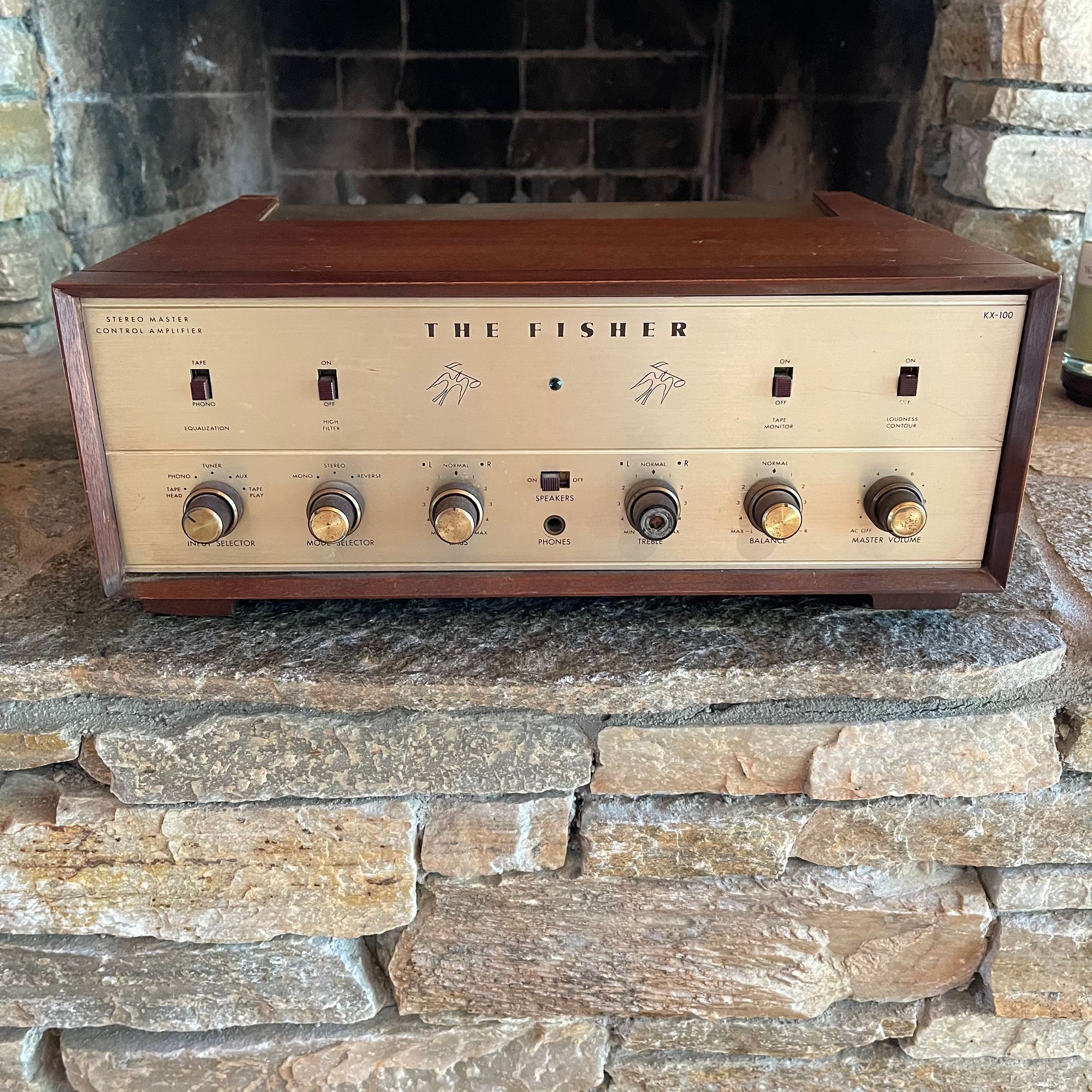
While it is getting more difficult to find good deals on vintage hifi, they are still out there. I picked up this non-working Fisher KX-100 as part of an entire system. The complicated part was it was in Raleigh, NC. I don't live there, but I have family there.
While I got a fair deal on the system, I had to figure out the logistics of getting it back to my home in Tahoe, NV. That is the current situation in the vintage hifi market. Deals are hard to come by, and you have to be willing to go out of your way to get them.
The good: the system was in original condition complete with manuals. The bad: it was dirty as hell and obviously hadn't worked in years. I looked for a tech to restore the amp, but eventually gave up and decided to do the work myself.
Basically, over the years, the capacitors go out of spec which can cause all sorts of audio problems and in a worst case situation can take out major components including tubes and transformers.
Fortunately outside the bad capacitors, the amp was still in good condition. I did order a full new set of tubes which is the most expensive parts required to rebuild the amp.
Parts
Since I had never done a recap before, I wasn't sure what I needed for the job. I decided to order a rebuild kit on eBay. This is a more expensive way to go, but you're basically paying someone to source all the parts you need, and to provide instructions on what to do.
The kit I purchased included a replacement for nearly every capacitor in the amp plus a replacement light (which I needed), fuse (which fortunately was still good), replacement diodes, and an in-rush limiter.
Unfortunately the capacitors (of which there are 7) for the power supply were not in prebuilt canisters as originally specified in the amp. As I will discuss, this lead to by far the most work in the project. I also ended up buying additional terminal strips as part of the part of the power supply capacitor work which were not part of the kit.
I also broke a few resistors in the process of working on the amp, and had to order replacements. The resistors I tested were still within spec. I also ordered wire and lead dressing to match the dressing that was in the amp.
Tools
This is where things can get expensive. If you are not planning on doing more of this kind of work, it might not be worth it to invest in the tools to do the job. Here's what I ended up needing:
- Soldering station
- Leaded solder
- Desoldering wick and pump
- Magnifying glass and light
- Helping hands
- Digital multimeter and additional leads
- Wire cutters
- Wire strippers
- Needle nose pliers
- Screwdriver
- Drill and 1/8" cobalt drill bits
- VARIAC (I have a vintage one which I double checked and it works perfect)
- Oscilloscope (mostly optional, but good for debugging)
I got frustrated finding a hum in the system and ultimately decided to buy a hobbyist quality scope. I could have probably lived with out it, but it did come in handy when trying to find a disconnected lead wire. I basically followed the input signal with the scope until it went dead.
Safety
I'm not an expert on electronics safety, and it is addressed in many places on the internet. Yes working on vintage electronics is dangerous. The voltage is over 400 DC at the anodes on the power tubes. Also capacitors can maintain charge after the system is shut off. After turning off the system, I doubled checked the voltages on all major power supply caps before starting any soldering work.
After making any significant circuit changes, I recommend bringing the system up slowly on a VARIAC and checking that the circuit voltages are still correct relative to each other.
With that said, I probably over estimated the risks of probing voltages with my multimeter and oscilloscope. Those devices, if placed in the right setting, present a high impedance load which has little effect on the circuit. Just make sure the black lead from your multimeter and the ground from your oscilloscope is connected to the chassis.
At one point I did fuck up by not understanding how current measurement worked on my multimeter. Current measurement DOES NOT present a high impedance load and shorts out circuits. Fortunately the worst thing that happened was I got a spark (but no shock) when I touched the probe to the cathode pin on a 12AX7 tube.
At that point I stopped, took at step back, and tried to better understand what the fuck I was doing. I would recommend calculating current across a cathode instead of trying to measure it directly unless you really know what you are doing.
Understanding the basics
I think it is helpful to understand the basics of how tube amplifiers work before diving in (although not strictly necessary, it helped me A LOT with debugging). I found Uncle Doug's YouTube videos on how guitar amps function really helpful for understanding tube amps in general. Hifi amps are a little different, especially push/pull amps like the Fishers, but the fundamentals are basically the same.
Also I highly recommend looking over the schematic and mapping it to the actual circuit you are working on. I actually found some resistors which were incorrect according the schematic. I was fortunate enough to have a paper copy, but most 60s amps have online schematics. It doesn't take long to read and understand schematics, even though I sometimes got lost when trying to map it to physical layout.
The work
I'm a software guy. I suck at soldering. My father-in-law who is an actual electrical engineer helped me with my soldering skills. My skills are passable, but not great. I had to reflow some complex joints multiple times. I did check my work with my multimeter as I went a long to make sure I wasn't shorting anything out.
In most cases replacing capacitors is not a big deal. You unsolder the existing cap, take note of how it wired in (maybe with a picture), double check the schematic, solder in the new cap, check your work, and move on. It is just a lot of manual labor.
I should note that the electrolytic capacitors used in the power supply have a polarity, and you must ensure the polarity is correct. The same goes for diodes.
Retrofitting Capacitor Cans
While replacing most capacitors is straight forward, this not the case for the capacitor cans. These canisters may contain one more capacitors and look like a silver or black cylinder on the top of the chassis. For all practical purposes, these cans are now obsolete and new designs do not use them.
There are few sources for capacitor can replacements including Hayseed Hamfest. If I had to do over, I would have ordered the capacitor cans pre-made. In fact I also have a Fisher KX-200 which needs to be recapped, and I ordered the can caps from Hayseed.
For other amps, such as my Dynaco ST-70, there maybe suitable aftermarket cans available. For instance I ordered this capacitor by CE Manufacturing for my ST-70.
Here's my recommendation on strategies for replacing capacitor cans in order of complexity:
1) Buy and install pre-made cans
2) Rebuild existing cans with new, discrete capacitors
3) Wire in new capacitors under the chassis
Unfortunately not knowing any better, the kit I bought didn't come with cans, only discrete capacitors. I looked at some videos regarding rebuilding existing cans, and probably wrongly concluded it would easier to wire in the new caps under the chassis. There are few problems with wiring in new caps under the chassis. First: physically placing the capacitors. Second: the new capacitors have to be rewired into the circuit.
The Fisher chassis is pretty complicated and full of parts. Trying to find room to squeezed in 6 or more capacitors under the chassis isn't easy. Second once you find a spot for them, you are going to have rewire them to common joints (absolutely making sure to double check the schematic). Going this route probably made the project an order of magnitude more complex.
Ultimately I bought new terminal strips, one for each can I was replacing, and drilled 3 1/8" holes in the chassis, and screwed them in. The steel of the chassis proved difficult to drill, and for some reason running the drill in reverse made the process go faster. This is part of the project I'm least happy with. I'm not great at running lead wires and soldering complex joints, and this required both. The final job doesn't look as clean as I would like, and I suspect, after I have some more experience under my belt, I'll revisit this implementation.
Testing
I wouldn't recommend this, but I basically recapped the entire unit before firing it up. When I did power it up, I brought it up SLOWLY on my vintage VARIAC. As the power came up, my father-in-law and I tested various parts of the circuit voltages according to the schematic. The voltages should be lower when running at lower voltages, but they should be the same relative to each other (higher voltages according to the schematic should be higher).
When we were convinced things basically looked ok, we brought it up to full voltage with speakers plugged in and gave it try. Surprisingly it worked! Damn that was an amazing feeling. Unfortunately there was a noticeable ground hum that I couldn't figure out.
The hum nearly drove me crazy. I even bought an oscilloscope to figure out what was going on. I narrowed it down to the tone controls, but I couldn't narrow it down further.
I asked for help on the internets and someone recommended testing with the bottom cover back on. For some reason I didn't think of this, but I'll be damned if it didn't work! The line-level inputs are dead quiet, although there is still a slight hum in the phono ground which I'm still trying to work out.
Take aways
You can do this! Yes it takes some special tools. Yes it takes patience. But overall the circuits and designs are pretty straight forward. You need to be careful, but not afraid. My biggest take away for your first project is to BUY THE CAPACITOR CANS PRE-MADE! This will greatly simplify the rewiring work.
The second take away is DO NOT DO FINAL TESTING WITHOUT THE BOTTOM COVER ON THE CHASSIS!
Also check your voltages relative to the schematic to make sure things are close.
It is like working on a complex puzzle. A puzzle which might accidentally kill you, but still a puzzle. I found the work a relaxing change of pace from my day job, and am looking forward to my next project. If you have any questions or comments feel free to email at christopher@baus.net