I'm a long time vintage 60s tube amp owner and I recently started working on my own components. This was my second project, after recapping my Fisher KX-100. If you are new to recapping vintage tube gear, I recommend reading that article first.
Acquisition
I bought this as part of larger system including a Dynaco PAS preamp, Dynaco Tuner, and Dual turntable. I've found it easier to get better deals if you buy the entire system rather than piece-by-piece, but given the current market for vintage HiFi equipment, I paid more for this system than I wanted to, and actually had to travel aways out of my way to purchase it.
Over the longer term this purchase will work out, but I feel like sellers, especially those selling original condition equipment with little knowledge, are expecting too much for their gear. There is a difference between a well sorted out piece and one which hasn't been turned on in 10 years.
On the upside, the gear did come with original documentation including build instructions and a schematic for the ST-70. It also came with a full set of tubes which were upgraded at some point in the amp's life.
Cleaning
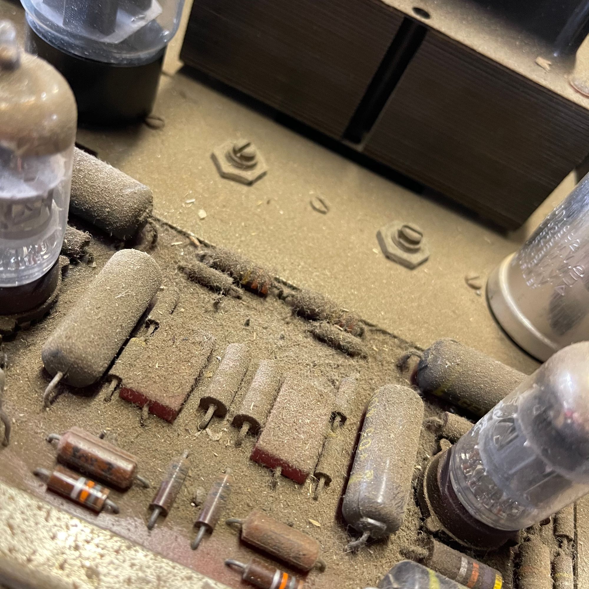
The Dynaco was stored in a handmade (and ugly) wooden case. It looked like it had been in there for years. When I pulled it out, the top of the unit had about an inch of dust on it. I carefully dusted it off and polished the chassis as best as I could. All things considered it came out pretty well. Fortunately the underside of the unit was still pretty clean.
Planning and Parts
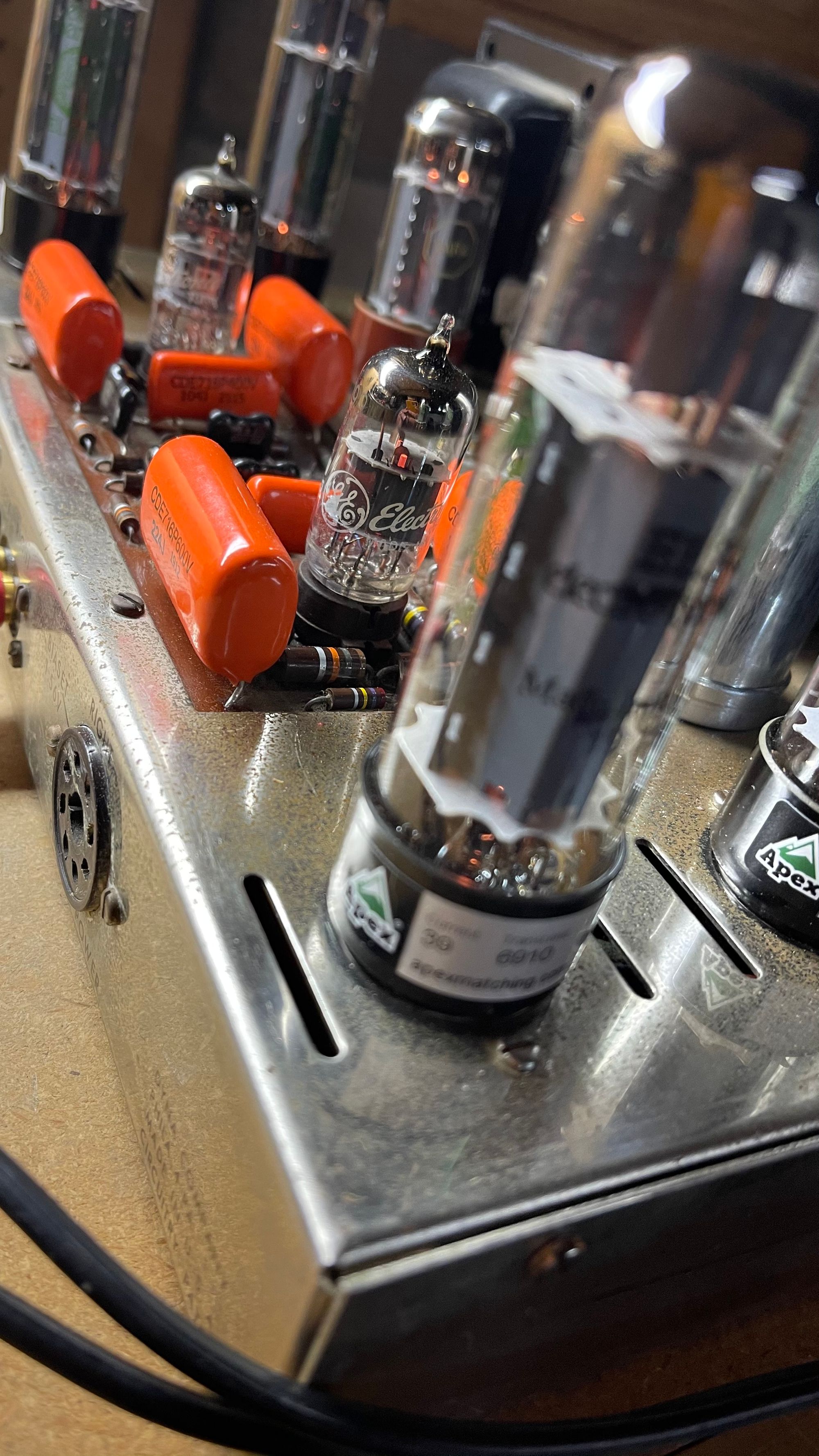
I decided to update all the capacitors in this unit including smaller pieces on the driver board, and the selenium rectifier. I also elected to keep the circuit stock, and continue to use the 7199 layout for better or worse. Unfortunately, the 7199s are out of production, and NOS tubes are around $150 for a pair. On the plus side, many of the old, used tubes are still serviceable. For this build I wanted to hear the ST-70 in it's more or less stock form.
I basically followed Dynaco guru, Bob Latino's, advice on parts. He recommended up-specing a few of the capacitors, and it worked out great. I reference Latino's posts at the end of the article, and here's a list of what I ordered and what they replaced.
I purchase most of my parts from Antique Electronic Supply (they have quick shipping and excellent support), so I added links to their site for the parts I used.
Power Supply / Bias circuit
- 1 CE Distribution 80, 40, 30, 20 uF @ 525V quad capacitor can - replaces the 30, 20, 20, 20 uF @ 500V capacitor can
- 1 1N4007 Diode - replaces the selenium rectifier
- 2 Mod Electronics 50 uF @ 100V - replaces bias caps of similar spec
- 1 3-way standoff - to mount the new diode to
Driver Board:
- 4 SBE 716P .22 uF @ 600V - replaces .10 uF @ 400V
- 2 SBE 716P .1 uF @ 400V - replaces .05 uF @400V
- 2 Silver Mica 82pF @ 500V - replaces same spec
- 2 Silver Mica 390pF @ 500V - replaces same spec (square caps)
Other:
- 3 prong power cord - replaces stock power cord which was cut and spliced together
- 5AR4 - replaced my incorrectly speced 5u4 tube
The build
The most time consuming part of the project was researching the parts, so hopefully this post will help out. I brought the amp up on my VARIAC and fortunately it worked with no modifications. I suspect some would have just put the amp into service, but the power supply capacitors and selenium rectifier should be replaced prior to serious usage. Selenium rectifiers are known to fail catastrophically, and, to make matters worse, they are toxic.
Upgrading the driver board is less critical from a safe operation standpoint, and I'll leave that decision to the owner, but I decided to recap the entire unit while I was in there.
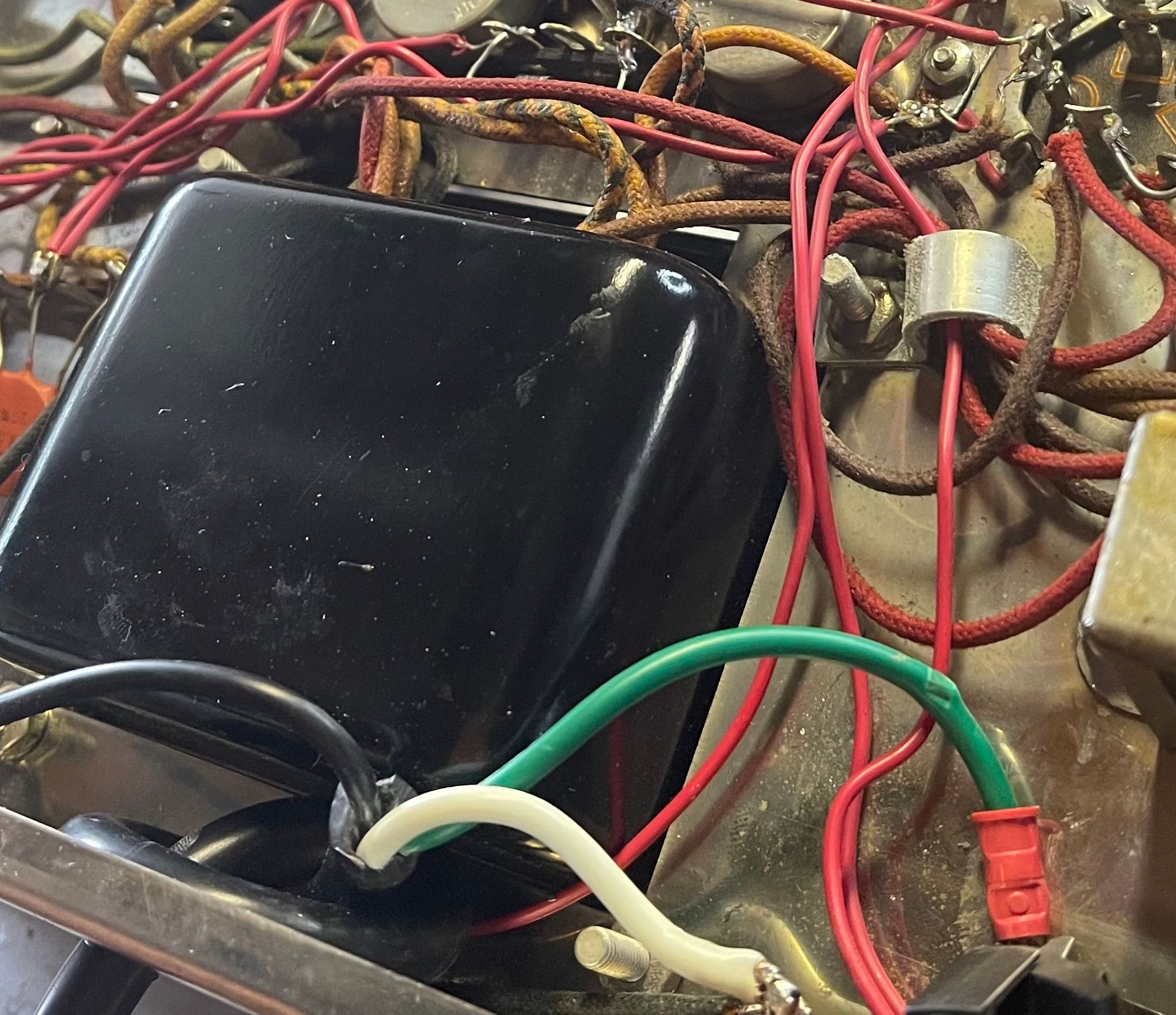
While most recaps won't require this, the power cord was in rough condition, and I decided to replace it with a 3 prong cord. There are discussions on whether using a grounded cord is better or worse for sound quality. But I had a 3 prong cord on hand, so that's what I used. I simply crimped a spade connector to the ground wire and attached it to the chassis.
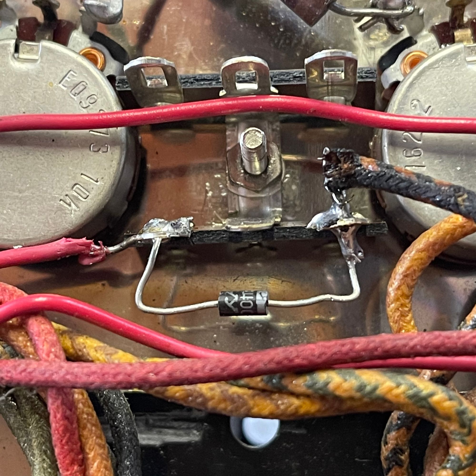
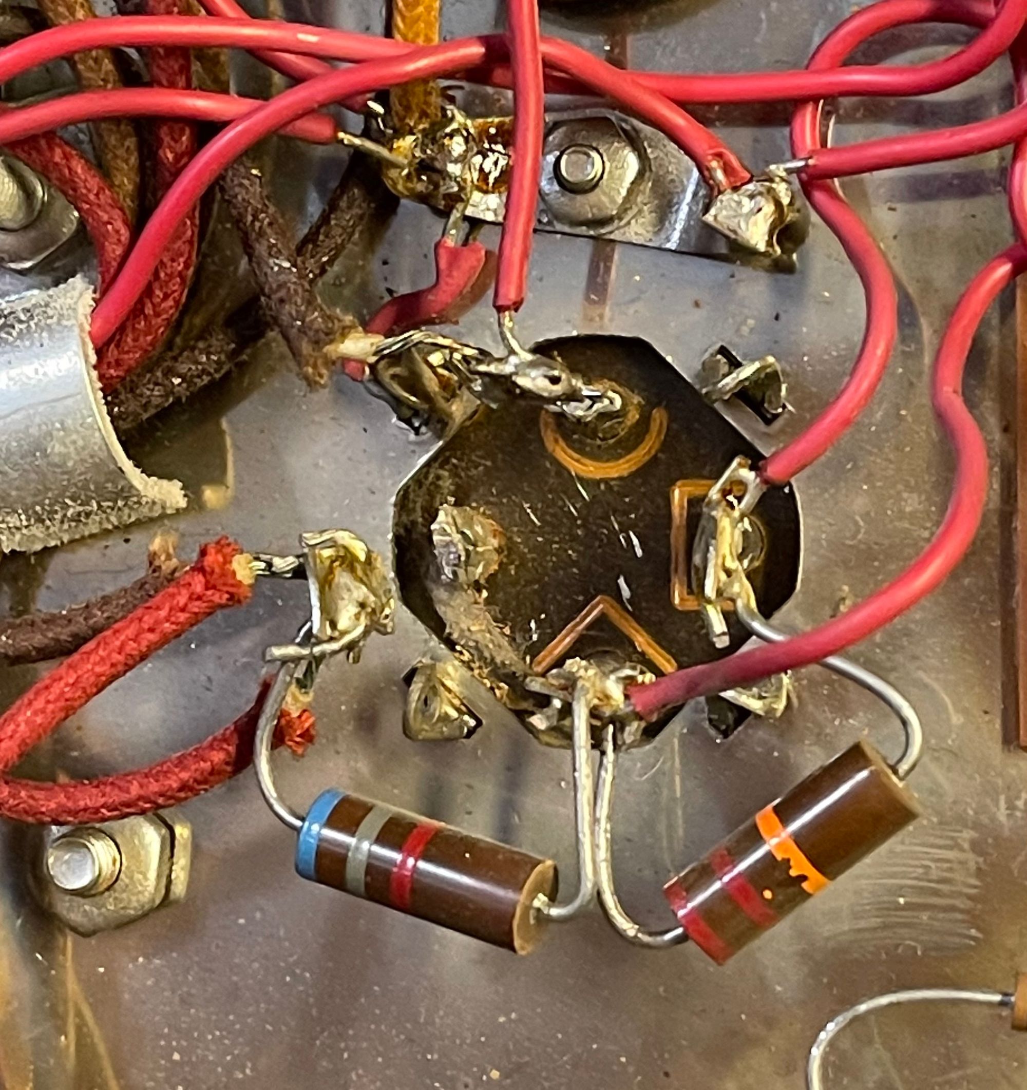
The selenium rectifier can be easily replaced with a $0.15 14007 diode. Just unscrew the existing rectifier and screw on a 3-way standoff. IMPORTANT the diode does have a specific polarity, so make sure the cathode (stripped side) of the diode is connected to the transformer lead. Some people recommend adding a resistor to the bias circuit to drop the bias voltage, but I didn't find that necessary. I did find an extra resistor hacked into the circuit (I think to compensate for a failing selenium rectifier), which I removed with no negative consequences.
Since the amp was in a working condition at the start of the project, I tested it after each component change to make sure things were still functioning properly. I didn't want to shot-gun in 14 or so new components and test it all at the end.
With the important selenium rectifier upgrade done, I moved on the capacitor can. It went pretty smoothly. I took a picture and cut off the the old standoffs from the can and unwired each one on at at time. Bob Latino recommended aligning the new can so the 80 section faced the back of the amp, and that alignment worked with no problems. Just make sure to rewire it exactly as it was and all should be good. I did have to run a short lead from common ground on the can to the chassis ground, as this was how my unit was initially wired.
The bias caps were easily replaced, and again just verified polarity, and tested the bias on the tubes. I was able to bias them in perfectly. At this point, with the power supply rebuilt, I'd consider the unit safe to use.
I decided to move onto the driver board. This unit has the original driver board. The boards are pretty crappy by modern standards. You have to be really, really careful not to pull up the traces. I will admit I pulled up a couple, both primarily by trying to remove or install cap with residual solder without have the joint hot enough.
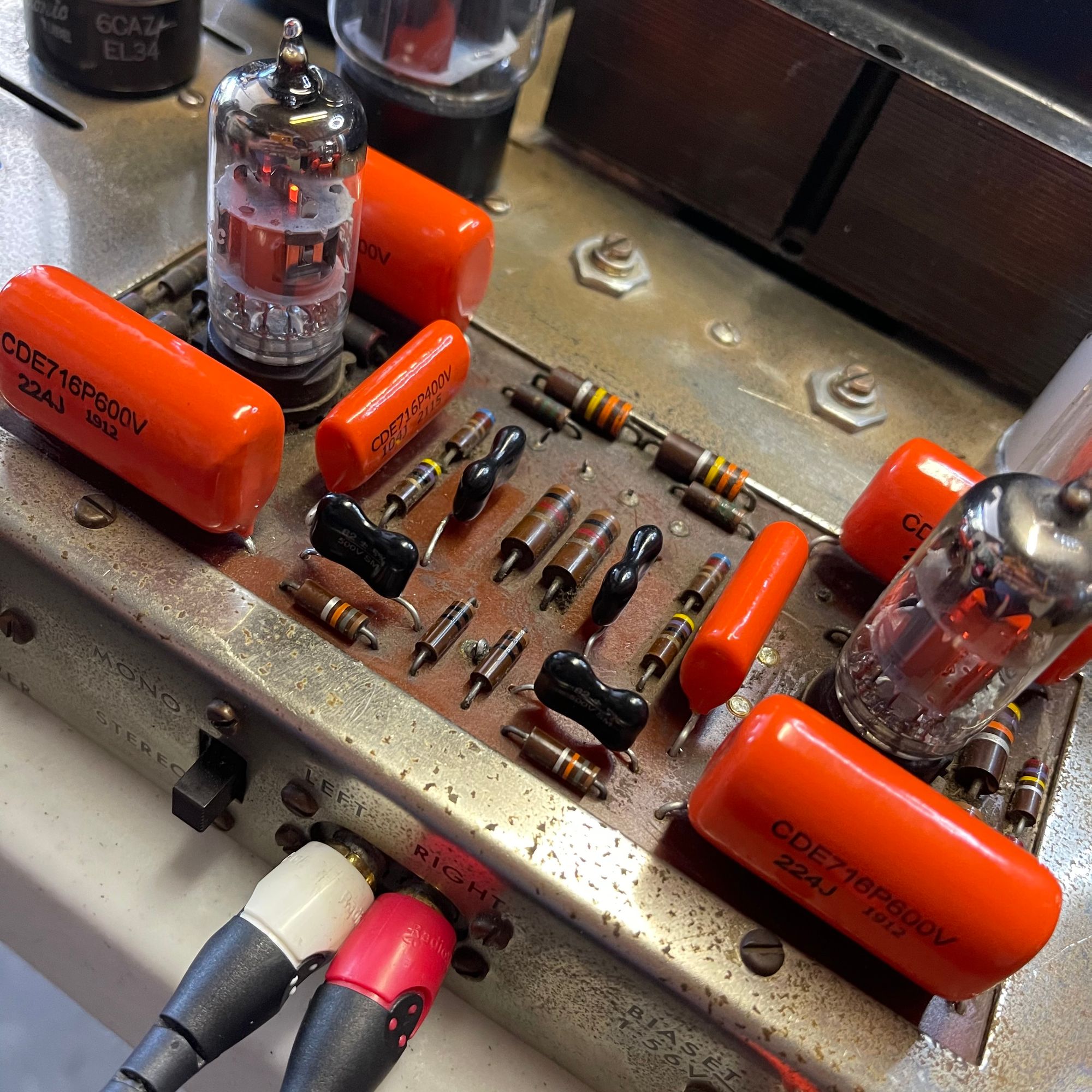
A desoldering gun, which I don't have, would come in really handy on this project. I was able to hack the cap leads to the traces to solve the problem satisfactorily, but I am still considering replacing the board with a modern example. This part is more tedious than difficult, and I just recommend going slow.
One last change I made was replacing the 5u4 rectifier tube with the correct 5ar4 spec. I have to admit I didn't look closely at the rectifier tube, but an astute follower on Instagram noticed this discrepancy. While it will work, it draws more current from an already overworked power transformer. Changing out the rectifier tube did lower the temperature of the power transformer, so I think it was a worthwhile change.
Conclusion
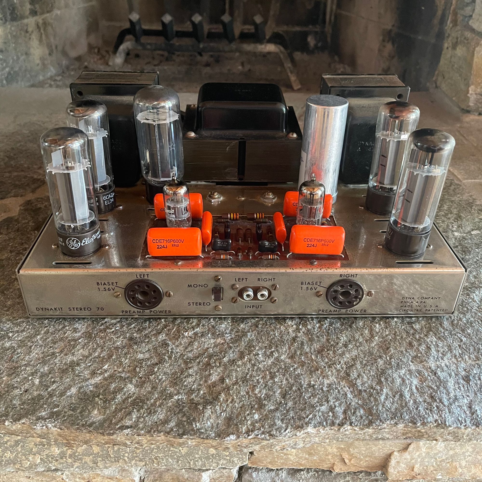
The Dynaco ST-70 is known as a unit which is easy to service and modify, and I have to agree with this assessment. There is plenty of room to work, and it uses a relatively simple and well understood circuit. Just be careful when working with the original driver board. They are known to be fragile and the traces will pull up if you aren't careful. I would definitely recommend this project to those new to tube amp repair.
Reference Links